1974 Briggs And Stratton Ignition Points Wiring Diagram
You are here: Home / Car and Motorcycle / Understanding Motorcycle Voltage Regulator Wiring

The article provides a detailed explanation regarding the various voltage regulator wiring configurations used in motorcycles. The article was submitted by Mr. Abu-Hafss.
Technical Specifications
After working on different voltage regulators, I feel to share my findings on your blog so that other people may also get benefit. Please insert the diagrams appropriately in the article. I will update further by providing examples of each type.
Thanks and regards
Abu-Hafss
UNDERSTANDING WIRING OF MOTORCYCLE VOLTAGE REGULATORS
Motorcycles are usually equipped with permanent magnet AC generators. The magnitude of the voltage produced by these generators depends upon the RPM of the engine. Despite these generators are specifically designed to produce about 13-15VAC at high RPMs, they do require a voltage regulator to provide a safe voltage for battery charging and for the electrical system. These generators could have single-phase or a three-phase winding. No matter the winding is single-phase or three-phase; all voltage regulator units have two parts i.e. Rectifier Section and Voltage Regulator Section. Here, we will only discuss various types of voltage regulators and not their internal circuits.
VOLTAGE REGULATORS FOR SINGLE-PHASE GENERATORS
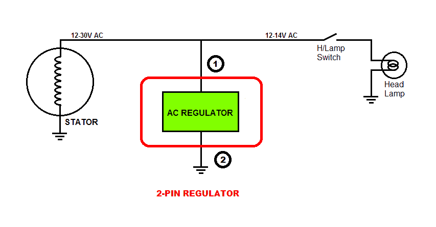
1) 2-pin Regulator: This type may be found on some small bicycles which do not have battery and only have Head Lamp & Tail Lamp. Since the incandescent bulbs work well on AC voltage, there is no rectifier section in this type of regulator. The circuit inside the unit regulates the AC voltage coming from the generator to 13.5 – 14 VAC for the bulbs. This regulator is basically an AC voltage regulator.
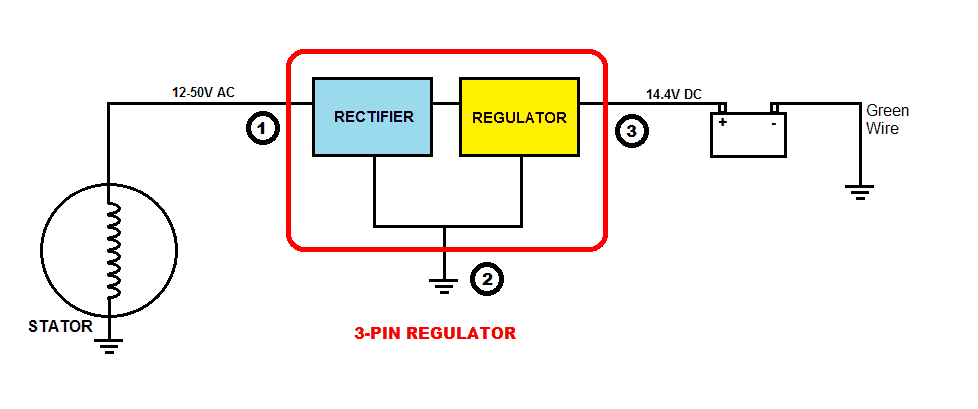
2) 3-pin Regulator: This type may be found on some motorcycles. In this system, we see that one end of the winding is grounded to the chassis of the bike, which is connected to the negative terminal of the battery. The other end of the winding supplies AC voltage to the rectifier section which converts it to DC voltage. Then it enters the Regulator section which maintains the output to an ideal 14.4V for charging a 12V battery (or 7.2V for a 6V battery) and powering the electrical system.
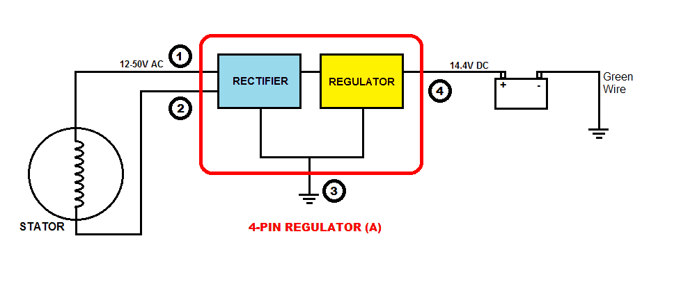
3) 4-pin Regulator (A): This type may be found on some motorcycles. In this system, both the ends of the winding go to the Rectifier section which converts AC to DC voltage and then the Regulator section regulates to 14.4V as discussed above.
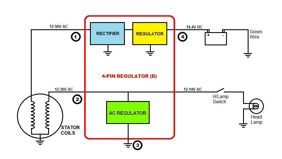
4) 4-pin Regulator (B): This is the most common type found on motorcycles with single-phase winding. In this system, the stator has dual windings. One supplies power for charging the battery and for the electrical system. The other supplies power exclusively for the Head Lamps and the Tail Lamps. This type of regulator unit is basically a combination of 3-pin Regulator and 2-pin Regulator. The 3-pin Regulator section provides 14.4V DC for the battery and the 2-pn Regulator provides 13.5 – 14V AC for the Lamps.
VOLTAGE REGULATORS FOR THREE-PHASE GENERATORS
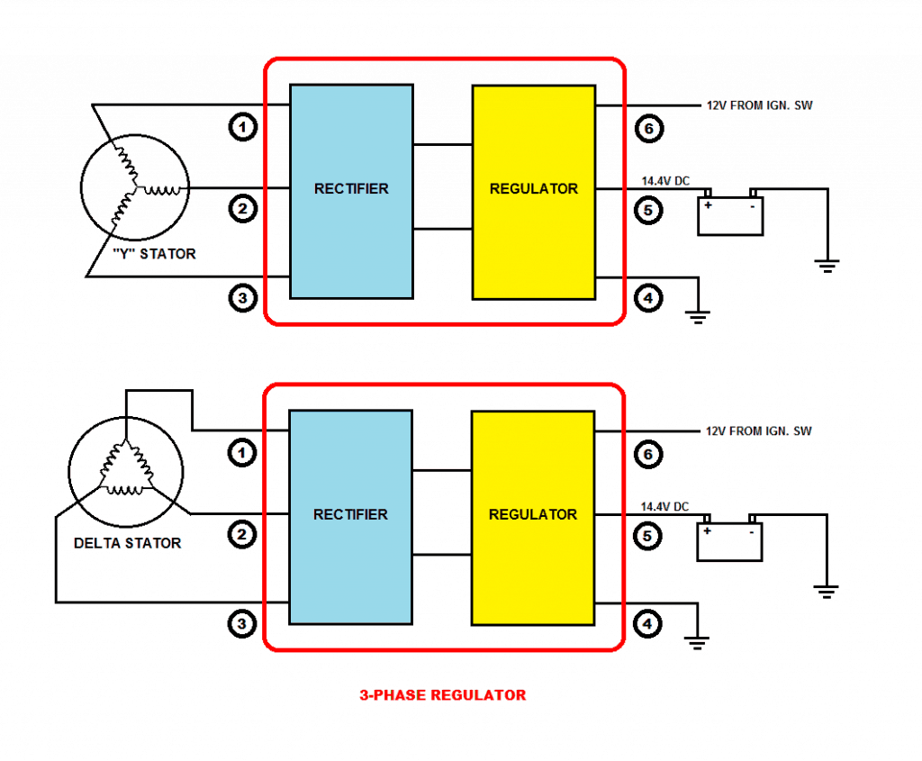
Three-phase windings are two types i.e. Y-type and Delta type.
The working principle of a regulator for three-phase generator is the same as 4-pin Regulator (A), but of course, the internal circuitry would be quite different.
An example of such 3-phase regulator can be seen in the article: motorcycle shunt regulator circuit using SCR
.
I am an electronic engineer (dipIETE ), hobbyist, inventor, schematic/PCB designer, manufacturer. I am also the founder of the website: https://www.homemade-circuits.com/, where I love sharing my innovative circuit ideas and tutorials.
If you have any circuit related query, you may interact through comments, I'll be most happy to help!

Reader Interactions
Source: https://www.homemade-circuits.com/understanding-motorcycle-voltage/
Posted by: pfleugerterresasays.blogspot.com
Posting Komentar untuk "1974 Briggs And Stratton Ignition Points Wiring Diagram"